Page 2 DV11 Operation and Maintenance FOREWORD This maintenance manual is designed to serve as a reference for DOOSAN Infracore (here after DOOSAN’s) customers and distributors who wish to gain basic product knowledge on DOOSAN’s DV11 Diesel engine. This economical and high-performance diesel engine (6 cylinders, 4 strokes, in-line, direct injection type) has been so designed and manufactured to be used for the overland transport or industrial purpose.
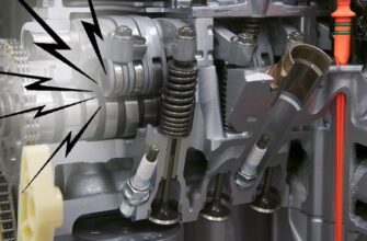
Page 32 DV11 Operation and Maintenance 2.3.16. Fuel injection system The fuel is stored under pressure in the common rail ready for injection. The injected fuel quantity is defined by the driver, and the start of injection and injection pressure are calculated by the ECU on the basis of the stored maps. The ECU then triggers the solenoid valves so that the injector (injection unit) at each engine cylinder injects accordingly.
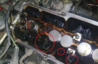
Page 33 DV11 Operation and Maintenance 2.3.18. Injector & high pressure connector Be careful to mix the foreign matter High pressure fuel into the injector and inside of the Injector harness connector nut connector connector for connecting the high O-ring Injector pressure at disassembly and check.
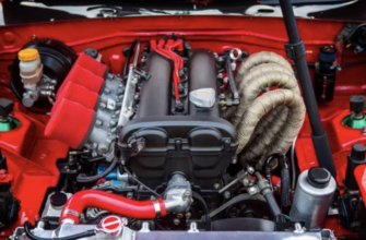
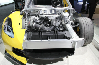
Page 34 DV11 Operation and Maintenance 2.3.20. Turbo charger The turbocharger needs not any specific maintenance. Every time of engine replacement, a leakage or clogging of oil pipes should be inspected. Air cleaner should be maintained carefully for nut or foreign material not to get in.
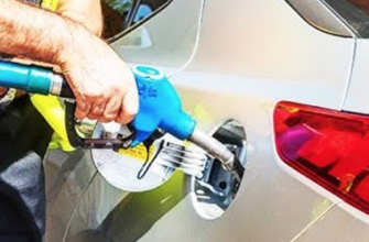
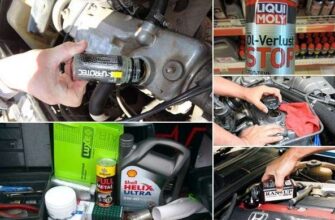
Page 35 DV11 Operation and Maintenance 2.3.21. Cooling system The engine has a liquid-cooling system. The fresh water pump is a maintenance-free by belt from the crankshaft pulley. Check the coolant level of the expansion tank by removing the expansion tank filler cap, and add coolant if necessary When injecting antifreeze solution, first drain out the old coolant from the cylinder block and radiator, and then clean them with cleaning solution.
Page 36 For the improper control might give the fatal damage to the cooling water pump and cylinder liners, detail care is needed. Since DV11 engine cylinder liner is wet type, particularly the cooling water control should be applied thoroughly. Technical Information.
Page 37 Operation and Maintenance The density of anti-freezing solution and additive for rust prevention is able to be confirmed by the cooling water test kit. (Fleetguard CC2602M or DOOSAN 60.99901-0038) How to use the cooling water test kit °C, loosen (1) When the cooling water temp. of engine is in the range of 10 ¡.
Page 38 DV11 Operation and Maintenance Amount of Anti-freeze in winter Ambient Cooling water (%) Anti-freeze (%) Temperature (°C) Over –10 2.3.24. Valve clearance adjust procedure After letting the #1 cylinder’s piston come at the compression top dead center by turning the crankshaft, adjust the valve clearances.
Page 39 DV11 Operation and Maintenance 1) Rotating the engine, let #6 cylinder overlap. 2) In time that #1 cylinder become the state of top dead center, adjust the valve clearance corresponding to ”.
Page 40 DV11 Operation and Maintenance Adjusting of valves (Type 1) Cylinder No Valve adjusting Exhaust Intake Exhaust Intake Exhaust Intake Intake Exhaust Intake Exhaust Intake Exhaust #1 cylinder top dead center ¡ Ý ¡ Ý ¡ Ý ¡ Ý ¡ Ý.
Page 41 DV11 Operation and Maintenance 2.3.25. Battery Inspect for any leakage of electrolytic solution owing to battery crack, and replace the battery in case of poor condition. Inspect for amount of electrolytic solution, and replenish if insufficient. Measure the gravity of electrolytic solution, if less than specified value (1.12 ¡ — 1.28), replenish.
Page 42 DV11 Operation and Maintenance 2.3.26. Alternator a) Alternator (24Vx60A) The alternator is fitted with integral silicon rectifiers. A transistorized regulator mounted on the alternator body interior limits the alternator voltage. The alternator should not be operated except with the regulator and battery connected in circuit to avoid damage to the rectifier and regulator.
Page 43 DV11 Operation and Maintenance b) Alternator (24Vx150A) 24V x 150A Regulator connector: AMP 250 Regulator connector — N terminal : cut off the charging lamp with detect the voltage by regulator. — A terminal : switching the regulator on sensing the output voltage.
Page 44 DV11 Operation and Maintenance 2.3.27. Starting motor The sliding-gear starter motor is flanged to the rear of the flywheel housing on the left-hand side. As parts of every engine overhaul, the starter pinion and ring gear should be cleaned with a brush dipped in fuel and then a coat of grease should be applied again.
Page 45: Diagnosis And Remedy
Page 55: Engine Inspection
Page 57: Engine Disassembly
3 minutes until the engine oil by-passes to the oil pan, then take off the filter. Unscrew the oil filter head fixing bolts and take off the oil filter head 3.1.20.
Page 65 DV11 Operation and Maintenance 3.1.22. Fuel pump housing cover Remove the fuel pump housing Fixing bolt cover fixing bolts and take off the Fuel pump housing fuel pump housing cover. cover Fuel pump housing cove and cylinder block should be handled as a set because they are tooled in pairs.
Page 66 DV11 Operation and Maintenance 3.1.25. Electric control unit Remove the electric control unit fixing bolts, then take off the electric control unit and bracket. Rubber cushion Bracket Electric control unit 3.1.26. Cylinder head cover Remove cylinder head cover fixing bolts and take off the cylinder head cover.
Page 67 DV11 Operation and Maintenance 3.1.28. Rocker arm Remove the rocker arm bracket fixing bolts and take out the rocker arm. Pull out the push rod. 3.1.29. Injector Remove the fuel high pressure Injector connecter fixing nuts and take off Injector bush the fuel high pressure connecter.
Page 68 DV11 Operation and Maintenance 3.1.30. Cylinder head Loosen the cylinder head fixing Cylinder head bolt bolts in the reverse order of assembling, and remove them all Disassembly order no. and then take the cylinder head out. Remove the cylinder head gasket and scrap it.
Page 69 DV11 Operation and Maintenance 3.1.33. Piston Remove the connecting rod cap bolts in the reverse order of assembling. Tapping the upper and lower of connecting rod caps lightly with an urethane hammer, separate them and take the bearings out. By pushing the piston assembly.
Page 70 DV11 Operation and Maintenance Remove the flywheel ring gear. Heat the ring gear evenly with a gas burner (up to 200 °C) to invite volumetric expansion. Tapping around the edges of the ring gear with a hammer and brass bar to remove it.
Page 71 DV11 Operation and Maintenance NOTES: Do not mingle with the metal bearings bearing caps randomly. prevent mixing, temporarily assemble the metal bearings corresponding bearing caps in turn. 3.1.38. Cam shaft & tappet Pull out the tappets from the cylinder block.
Page 72: Measurement And Inspection On Major Parts
0.321mm Assemble the connecting rod to.
Page 93 DV11 Operation and Maintenance 3.3. Engine Reassembly 3.3.1. Preparation and precaution before and after engine reassembly Clean all the parts thoroughly and also clean thoroughly by blowing into each passage of oil and cooling water. Disposition the various special and general tools for assembling in order.
Page 94 DV11 Operation and Maintenance 3.3.3. Oil spray nozzle Tighten the oil injection nozzle flange with hollow screws. Assemble the oil injection nozzle with the fixing bolts. Hollow screw 7 kg.m Torque Fixing bolt 1.2 kg.m 3.3.4. Crank shaft Put the wear ring into the heater to heat it up to 150 ∼.
Page 95 DV11 Operation and Maintenance Coat the crankshaft journal and pin parts with engine oil, and after fitting the main bearing into the bearing cap and assemble it to the cylinder block making sure of the number in order not to change the bearing cap.
Page 96 DV11 Operation and Maintenance 3.3.5. Tappet Coat the tappet wholly clean oil and push in the tappet hole of the cylinder block. 3.3.6..Cam shaft Coat the cam bush of cylinder Camshaft gear block and camshaft with engine oil. Assemble bush.
Page 97 DV11 Operation and Maintenance Coat the oil seal (P.T.F.E.) with Thrust washer lubricating oil and assemble the oil Thrust washer seal carefully for it not to deviate or fixing bolt be damaged by means of special tool. (Mandrel for assembling.)
Page 98 DV11 Operation and Maintenance 3.3.8.. Fly wheel Installation of flywheel ring gear with a gas burner, heat the ring gear evenly until heat expansion takes place, then install it using a hammer. Do not allow the temperature of the ring gear to exceed 200°C (392°F).
Page 99 DV11 Operation and Maintenance 3.3.9. Front oil seal holder After placing the oil seal in the oil seal holder hole properly, press it in with a special tool. (Be careful for oil seal not be damaged.) Attach a gasket at the oil seal holder.
Page 100 DV11 Operation and Maintenance Coat the pistons and connecting rod bearings sufficiently with clean engine oil. By means of a special tool, insert the piston rings and adjust the angles between the ring gaps at 120°. Identify the mark «Y» or «TOP» on the ring end to prevent the top and “Y”.
Page 101 DV11 Operation and Maintenance (1) First step : Coat the bolts with engine oil. (2) Second step: Engage 2¡ — 3 threads by hands. (3) Third step : Tighten to about 7kg.m with wrench. (4) Fourth step : By means of torque wrench tighten to 10 kg.m.
Page 102 DV11 Operation and Maintenance Assemble pump pressure regulating valve tightening the fixing bolts. Oil pump back lash 0.1
0.45 mm Attach a gasket at the surface of the oil pump where the oil suction pipe is to be installed, and install the oil suction pipe by tightening the fixing bolts.
Page 103 DV11 Operation and Maintenance 3.3.13. Oil pan Clean thoroughly the gasket that is projecting at the junction parts of front oil seal holder and flywheel housing of cylinder block’s lower face with a scraper. In the process of gasket removal, be careful for the gasket pieces not to get into the engine inside.
Page 104 DV11 Operation and Maintenance Assemble a gasket fitting with the fixing pin of cylinder block. Position cylinder head assembly on the cylinder block aligning with its dowel pin. (Take care not to damage the head gasket.) Part no. Coat the cylinder head bolts with.
Page 105 DV11 Operation and Maintenance 3.3.16. Injector Clean all the parts thoroughly and Injector Fixing bolt be careful not to fall into the foreign Injector bush material. Fuel high pressure Especially take deeper care on fuel connecter line from common rail up to injector.
Page 106 DV11 Operation and Maintenance 2) Clean the holes which an injector and a high pressure connector will be put into before they are assembled. Engine oil and fuel that might went into during disassembly should be wiped out especially for the holes where a fuel high pressure connector &.
Page 107 DV11 Operation and Maintenance 7) The injector and high pressure connector should be assembled correctly by the following order. Finally tighten the fixing bolt of injector up to the specified torque while the high pressure connector is still pre-tightened. Finally assemble the high pressure connector. Tighten the fixing nut of high pressure connector according to the specified torque by the torque wrench.
Page 108 DV11 Operation and Maintenance Torque 6.2 kg.m Adjust the valve clearance as reference of major maintenance part. 3.3.18. Engine brake Put the engine brake on the rocker arm of the cylinder head, then assemble the engine brake. Adjust the clearance of the slave.
Page 109 DV11 Operation and Maintenance 3.3.20. Fuel high pressure pump Assemble the gear of the fuel high pressure pump by using specified tool. Gear nut torque 11±0.5 kg.m Driving gear Fuel high pressure pump Install the fuel high pressure pump on the backside of the fly wheel housing.
Page 110 DV11 Operation and Maintenance 3.3.22. Common rail & high pressure pipe Assemble the common rail on the cylinder block. Install the fuel high pressure pipe between the common rail and the fuel high pressure connector, then tighten the cylinder by cylinder with specified torque.
Page 111 DV11 Operation and Maintenance 3.2.24. Exhaust manifold Attach a new gasket to the exhaust manifold. Fix the pipe that is connected exhaust manifold by tightening the fixing bolts. Assemble both sides in the same method as above. Torque 8.0 kg.m 3.3.25.
Page 112 DV11 Operation and Maintenance Refer to the chapter of 3.4 about relation of the common rail system Rubber cushion and the electric control unit. Bracket Electric control unit 3.3.26. Crankshaft speed sensor Measure the clearance of the Crankshaft speed sensor.
Page 113: Reassembly
Page 120: Fuel Injection System
Page 134: Electrical System
Page 147: Engine Brake
Page 158: Engine Diagnostic
Page 159: Engine Diagnostic
Page 169: Commissioning And Operation
Page 171: Inspections After Starting
3 kg/cm at idling and 3
4.9 bar) at maximum speed. If the pressure fluctuates at idling or does not reach up to the expected level at high speed, shut down the engine immediately and check the oil level and the oil line leakage.
Page 173: Operation In Winter Time
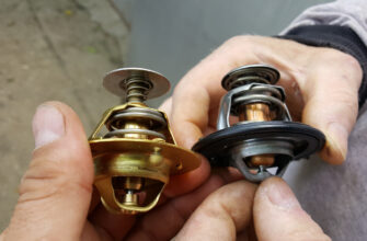
85°C) after continuous operation, examine the thermostat or the other cooling lines.
Page 176: Maintenance And Care
Page 179: Cooling System
Page 181: Adjustment Of Valve Clearance
Page 183: Tightening The Cylinder Head Bolts
Page 185: Maintenance Of Major Components
Page 189: Lubrication System
Page 192: Turbo Charger
3.0 kg/cm abnormal wear or stuck may be At full load : 3.0
5.5 kg/cm caused.
Page 197 DV11 Operation and Maintenance 3) Lubricating system In the lubricating system, a care must be paid to the oil quality and oil element replacement cycle. For the oil deterioration of turbocharger equipped engine, needless to speak of engine assembly itself, influences badly to the turbocharger too.
Page 198 DV11 Operation and Maintenance (1) Rotor axial direction end play Turbine wheel Magnitic vise chamber Move the turbine shaft in axial Dial direction gauge Standard : 0.117
0.20mm Limit of wear : 0.24mm (2) Rotor radial direction end play Dial Magnetic vise.
Page 199 DV11 Operation and Maintenance (1) Lubricating system Before reassembling the turbocharger onto the engine, inject new oil in the oil inlet port and lubricate the journal and thrust bearings by rotating them with hand. Clean not only the pipes installed between the engine and oil inlet port but also the oil outlet pipe and check them for damage or foreign matters.
Page 200 DV11 Operation and Maintenance 5.3.7. Diagnostics and troubleshooting Complaints Possible causes Corrections 1. Excessive black smoke 1) Air cleaner element clogged Replace or clean 2) Restrictions in air duct Check and correct 3) Leakage at intake manifold Check and correct.
Page 201: Air Cleaner
Page 203: Belt
Page 206: Special Tool List
φ128.010 φ128.122 cylinder liner the rim of the upper side Liner’s roundness &. Page 212 DV11 Operation and Maintenance Stand value Limit Group Part Inspection item Correction Remark for assembly for use 2nd ring 0.80
0.95 inside diameter : φ128 Oil ring 0.40
0.70 Piston ring Top ring 0.105
0.155 0.20 Limit for use is if. Page 213 DV11 Operation and Maintenance (unit: mm) Stand value Limit Group Part Inspection item Correction Remark for assembly for use Measure in Major Radial run-out of journal Correct 0.01 horizontal and and pin with a grinder moving vertical directions parts Outside diameter of Use under sized φ103.98
φ104.00.
Page 214 DV11 Operation and Maintenance Stand value Limit Group Part Inspection item Correction Remark for assembly for use Torque value of Clean out foreign Coat the bolt connecting rod bearing 10kg.m + 90 objects on joining with engine oil cap bolt (kg.m)
Page 215 DV11 Operation and Maintenance Stand value Limit Group Part Inspection item Correction Remark for assembly for use Valve seat φ43.50
φ43.75 Intake assembly part’s inner diameter of φ41.50
φ41.75 Exhaust cylinder head φ43.554
φ43.570 Intake Diameter of valve seat Exhaust φ41.554
φ41.570 Valve seat assembly part’s depth of. Page 216 DV11 Operation and Maintenance Stand value Limit Group Part Inspection item Correction Remark for assembly for use Clearance between Replace bush rocker arm shaft & 0.031
0.073 0.14 or shaft rocker arm bush Replace or Run-out of push rod correct Tappet assembly part’s inner diameter of φ20.000
φ20.021. Page 217 DV11 Operation and Maintenance Stand value Limit Group Part Inspection item Correction Remark for assembly for use Damage of oil filter Clean or element replace By-pass valve pressure 1.8
2.4 Oil filter (kg/cm Oil filter control valve 4.3
4.7 pressure (kg/cm Radiator &. Page 218 DV11 Operation and Maintenance Stand value Limit Group Part Inspection item Correction Remark for assembly for use Projection height of nozzle from the Replace 2.4
2.9 cylinder head surface(mm) sealing B grade φ90.000